Figure.1
| PolarSPARC |
Hands-On with RFID/NFC
| Bhaskar S | 09/08/2024 |
Overview
Radio Frequency Identification (or RFID for short) is a form of contactless communication technology that uses electromagnetic radio waves to communicate or identify objects wirelessly, which can be used in a wide variety of use-cases such as Access Control, Asset Tracking, Inventory Management, Transit Pass, etc.
The RFID ecosystem basically consists of the following two entities:
Target :: referred to as the RFID Tag, it consists of an Antenna connected to an RFID Microchip with a small amount of internal storage memory of about 1 Kb
Initiator :: referred to as the RFID Reader/Writer, it consists of an Antenna connected to an RFID Microcontroller that emits signals using radio waves and processes the received data from an RFID Tag. Note that an RFID Reader/Writer can also write data to an RFID Tag
When an RFID Tag comes in close proximity to an RFID Reader/Writer, it responds back to the RFID Initiator with the data stored in its internal memory.
Note that An RFID Tag can either be Active or Passive.
Active RFID Tags have an attached power source (in the form of a battery) enabling them to send data over longer distance (around 100 metres).
Passive RFID Tags have no attached power source and are activated or energized by the radio waves emitted by the RFID Reader/Writer. As a result, Passive Tags have limited range and lower performance.
Near Field Communication (or NFC for short) is an extension of RFID that operates in the High Frequency range of 13.56 MHz, has more capabilities, and has wider applications especially in the Tap-and-Go Payments space.
RFID works over distances of 20 metres or more (for Active Tags), while NFC has limited range of up to 20 cms.
The data exchanged between a NFC Initiator and a NFC Target is using the NFC Data Exchange Format (or NDEF for short).
Every NDEF message contains one or more NDEF Records. Each NDEF Record has a particular record type, a unique ID, a length, and a payload for custom UTF-8 string data. Note that the RFID Targets DO NOT format their data exchange in NDEF format.
The internal storage memory is arranged as Sectors and Blocks. There are 16 sectors and each sector consists of 4 blocks. Each block can hold up to 16 bytes of data. Hence, the internal memory size is 1 Kb (16 sectors x 4 blocks x 16 bytes).
One restriction - the first block of the first sector and the last block of each sector is NOT writeable.
The first block of the first sector contains the unique identifier set by the manufacturer.
The last block of each sector is the Trailer block that contains information about the sector, such as the sector number, the number of blocks in the sector, and the checksum, etc.
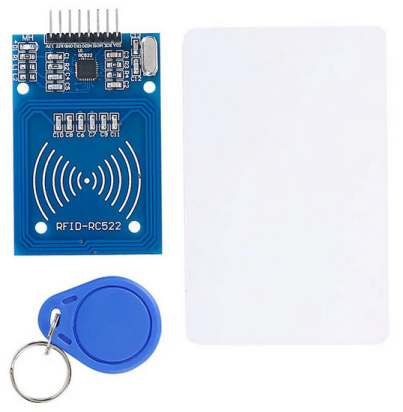
For the hands-on demonstration in this article, we will make use of a Raspberry Pi 4 along the Mifare RC522 Module as shown in the illustration below:
The Mifare RC522 is a very low-cost RFID (Radio-frequency identification) reader and writer that is based on the MFRC522 microcontroller.
Mifare RC522 exchanges data using the Serial Peripheral Interface (or SPI for short) protocol to communicate with RFID Tags.
Mifare RC522 does support a two-way data transmission rate up to 424 Kbps as well as a rapid CRYPTO1 encryption algorithm to verify Mifare products.
Serial Peripheral Interface (or SPI for short) is a synchronous data bus that is commonly used for exchanging data between microcontrollers and small peripheral devices such as shift registers, sensors, etc.
SPI is a synchronous data bus meaning it uses separate lines for data and a clock in order to keep both the sender and the receiver in perfect sync. The clock is an oscillating signal that tells the receiver exactly when to sample the bits on the data line.
With SPI, only the controller (or the Master) generates the clock signal (marked as SCK for Serial ClocK) to send to the peripheral (or the Slave).
When data is sent from the controller to a peripheral, it is sent on a data line referred to as MOSI (Master Out/Slave In). If the peripheral needs to send a response back to the controller, the controller will continue to generate a pre-arranged number of clock cycles, and the peripheral will put the data another data line referred to as MISO (Master In/Slave Out).
Setup
The setup will use a Raspberry Pi 4 running Raspbian OS.
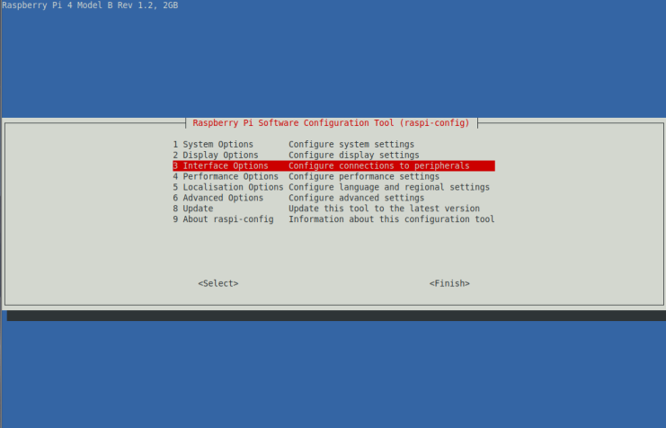
Once the Raspberry Pi 4 boots up, open a terminal window and execute the following command:
$ sudo raspi-config
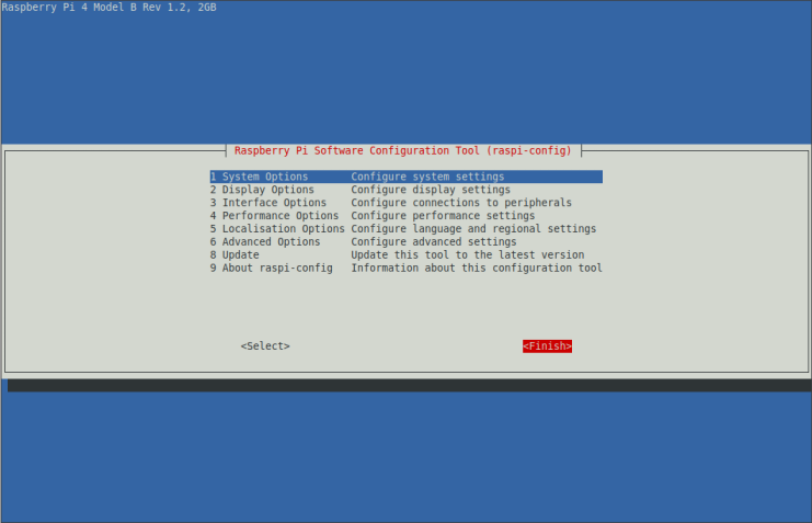
This will launch the configuration tool and navigate to Interface Options as shown below:
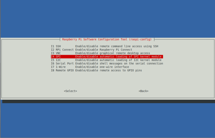
Press the ENTER key on the Interface Options and navigate to SPI as shown below:
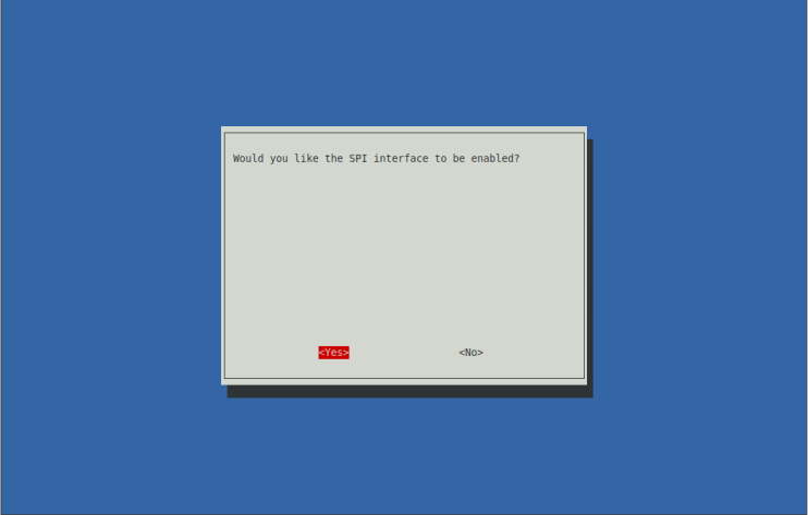
Select <Yes> to enable SPI and press the ENTER key as shown below:
One would be taken back to the main screen. Select <Finish> and press the ENTER key as shown below:
At this point, the SPI option should be enabled on the Raspberry Pi 4.
To validate SPI has been enabled, open a terminal window and execute the following command:
$ lsmod | grep spi
The following would be a typical output:
spidev                 16384  0
spi_bcm2835            20480  0
To create a directory and a Python virtual environment for the hands-on demo, execute the following commands in the Terminal:
$ cd $HOME
$ mkdir -p Projects/RFID
$ cd Projects/RFID
$ python3 -m venv venv
$ source venv/bin/activate
There will be no output.
To install the Python module for interfacing with devices using SPI, execute the following command in the Terminal:
$ python3 -m pip install spidev
The following would be a typical output:
Looking in indexes: https://pypi.org/simple, https://www.piwheels.org/simple
Collecting spidev
  Downloading spidev-3.6.tar.gz (11 kB)
  Installing build dependencies ... done
  Getting requirements to build wheel ... done
  Preparing metadata (pyproject.toml) ... done
Building wheels for collected packages: spidev
  Building wheel for spidev (pyproject.toml) ... done
  Created wheel for spidev: filename=spidev-3.6-cp311-cp311-linux_aarch64.whl size=42607 sha256=27f4da897dbd68370bad077cedbcb422fe176733bb90821d9be81e6636bcbd06
  Stored in directory: /home/bswamina/.cache/pip/wheels/44/f9/7b/01bb1f281eedaaa562943e27c78dee683ee6e7f3bf2f437101
Successfully built spidev
Installing collected packages: spidev
Successfully installed spidev-3.6
To install the Python module for interacting with the Raspberry Pi 4 GPIO interface, execute the following command in the Terminal:
$ python3 -m pip install RPi.GPIO
The following would be a typical output:
Looking in indexes: https://pypi.org/simple, https://www.piwheels.org/simple
Collecting RPi.GPIO
  Using cached RPi.GPIO-0.7.1.tar.gz (29 kB)
  Preparing metadata (setup.py) ... done
Installing collected packages: RPi.GPIO
  DEPRECATION: RPi.GPIO is being installed using the legacy 'setup.py install' method, because it does not have a 'pyproject.toml' and the 'wheel' package is not installed. pip 23.1 will enforce this behaviour change. A possible replacement is to enable the '--use-pep517' option. Discussion can be found at https://github.com/pypa/pip/issues/8559
  Running setup.py install for RPi.GPIO ... done
Successfully installed RPi.GPIO-0.7.1
To install the Python module for interacting with Mifare RC522, execute the following command in the Terminal:
$ python3 -m pip install mfrc522
The following would be a typical output:
Looking in indexes: https://pypi.org/simple, https://www.piwheels.org/simple
Collecting mfrc522
  Using cached https://www.piwheels.org/simple/mfrc522/mfrc522-0.0.7-py3-none-any.whl (18 kB)
Requirement already satisfied: RPi.GPIO in ./venv/lib/python3.11/site-packages (from mfrc522) (0.7.1)
Requirement already satisfied: spidev in ./venv/lib/python3.11/site-packages (from mfrc522) (3.6)
Installing collected packages: mfrc522
Successfully installed mfrc522-0.0.7
This completes the necessary software setup.
Shutdown the Raspberry Pi 4 in order to make the hardware connection with Mifare RC522.
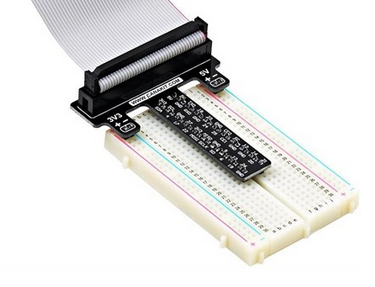
To connect the Raspberry Pi 4 to Mifare RC522, we will make use of a breadboard with the GPIO Cobbler Connector as shown in the illustration below:
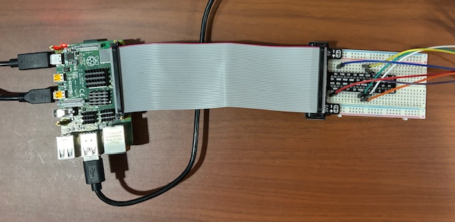
The following illustration depicts how the Raspberry Pi 4 is connected to the breadboard via the GPIO Cobbler Connector:
From the Mifare RC522 picture in Figure.1, we observe it has 8 pins which are as follows (from right to left):
SDA :: the Serial Data Adapter pin used as the data exchange bus
SCK :: the Serial Clock pin used to connect to the controller clock
MOSI :: the Master Out/Slave In pin used for clock signal out of the controller to the peripheral
MISO :: the Master In/Salve Out pin used as drive clock signal into the controller
IRQ :: the Interrupt Request pin used to generate interrupts
GND :: the Ground pin used for ground
RST :: the Reset pin
3.3v :: the 3.3 volt pin for power
To make a proper connection between Mifare RC522 and Raspberry Pi 4, the pins from Mifare RC522 must be connected to the following GPIO pins using jumper wires:
SDA pin to GPIO pin 24
SCK pin to GPIO pin 23
MOSI pin to GPIO pin 19
MISO pin to GPIO pin 21
GND pin to GPIO pin 24
RST pin to GPIO pin 22
3.3v pin to GPIO pin 1
The following illustration depicts how the Mifare RC522 is connected to the breadboard via the GPIO Cobbler Connector and the jumper wires:
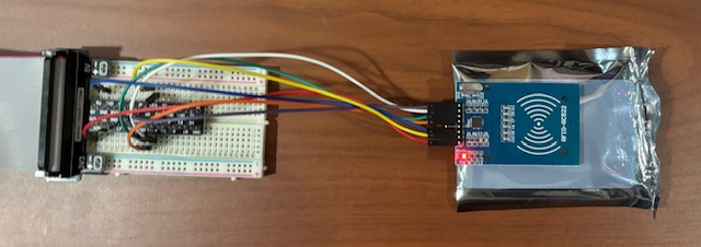
With all the connections complete, it is time to power-up the Raspberry Pi 4. Note that if the wires are connected correct, the LED on the Mifare RC522 will turn on RED.
Hands-on with RFID/NFC
To perform a basic RFID Tag read test, execute the following code snippet in a new Terminal:
import time

import RPi.GPIO as GPIO

from mfrc522 import SimpleMFRC522

def setup():
    GPIO.setwarnings(False)
    reader = SimpleMFRC522()
    return reader

def cleanup():
    GPIO.cleanup()

def main():
    while True:
        print('Hold Tag near Reader =>')

        id, txt = reader.read()

        print(f'ID -> {id}')
        print(f'Text = {txt}')

        time.sleep(1)

if __name__ == '__main__':
    reader = setup()

    try:
        main()
    except KeyboardInterrupt:
        cleanup()
By holding the provided card near the RFID Reader, one would see the following output:
Hold Tag near Reader =>
ID -> 632189491926
Text =
Trying to hold any other card, such as a credit card near the RFID Reader, one would see the following output:
Hold Tag near Reader =>
AUTH ERROR!!
AUTH ERROR(status2reg & 0x08) != 0
ID -> 584208502871
Text =
The code snippet above uses the SimpleMFRC522 class to get started quickly. For more control of the various steps, one can use the MFRC522 class.
To perform a more fine-grained RFID Tag read test, execute the following code snippet in a new Terminal:
import signal
import sys
import time

import RPi.GPIO as GPIO

from mfrc522 import MFRC522

loop = True
trailer_block = 3
auth_key = [0xFF, 0xFF, 0xFF, 0xFF, 0xFF, 0xFF]
block_nums = [0, 1, 2]

def uid_to_num(uid):
  n = 0
  for i in range(0, 5):
      n = n * 256 + uid[i]
  return n

def handle_ctrl_c(signal, frame):
    global loop
    loop = False
    cleanup()
    sys.exit()

def setup():
    GPIO.setwarnings(False)
    signal.signal(signal.SIGINT, handle_ctrl_c)
    reader = MFRC522()
    return reader

def cleanup():
    GPIO.cleanup()

def read_tag(rdr):
    while loop:
        st, tt = rdr.MFRC522_Request(reader.PICC_REQIDL)
        if st != rdr.MI_OK:
            continue
        st, id = rdr.MFRC522_Anticoll()
        if st != rdr.MI_OK:
            continue
        break
    return tt, id

###
#
# Sectors => 0 through 15
#
# Each Sector -> Blocks => 0 through 3
#
# Each Block -> 16 bytes => 00 00 00 00 00 00 00 00 00 00 00 00 00 00 00 00
#                           -----------------             -----------------
#                           ----> Key A <----             ----> Key B <----
#
# Sector 00 -> Block => 00, 01, 02, 03
# Sector 01 -> Block => 04, 05, 06, 07
# Sector 02 -> Block => 08, 09, 10, 11
# ...
# Sector 15 -> Block => 60, 61, 62, 63
#
# Trailer Blocks -> 03, 07, 11, ... 63
#
# Read a Block -> (3 * Sector + Sector + Block) => Sector 0 to 15, Block 0 to 3
#
###

def main():
    while loop:
        print('Hold Tag near Reader =>')
        print('Read Tag ...')

        tag_type, uid = read_tag(reader)

        print(f'Tag ID -> {uid_to_num(uid)}')
        print(f'Tag Type -> {tag_type}')

        print('Set Tag ID ...')

        reader.MFRC522_SelectTag(uid)

        print('Auth ...')

        ### To Read blocks from a particular sector, provide the appropriate trailer block number

        status = reader.MFRC522_Auth(reader.PICC_AUTHENT1A, trailer_block, auth_key, uid)
        if status != reader.MI_OK:
            print('Auth Failed !!!')
            reader.Close_MFRC522()
            break

        print(f'Read Blocks -> {block_nums}')

        buf = []
        txt = ''
        for block_num in block_nums:
            buf = reader.MFRC522_Read(block_num)
            if buf:
                txt = ', '.join(hex(b) for b in buf)
                print(f'Block {block_num} => {txt}')

        print('Stop Crypto1 ...')

        reader.MFRC522_StopCrypto1()

        time.sleep(1)

if __name__ == '__main__':
    reader = setup()

    try:
        main()
    except:
        cleanup()
By holding the provided card near the RFID Reader, one would see the following output:
Hold Tag near Reader =>
Read Tag ...
Tag ID -> 632189491926
Tag Type -> 16
Set Tag ID ...
Auth ...
Read Blocks -> [0, 1, 2]
Block 0 => 0x93, 0x31, 0x6e, 0x1a, 0xd6, 0x8, 0x4, 0x0, 0x62, 0x63, 0x64, 0x65, 0x66, 0x67, 0x68, 0x69
Block 1 => 0x0, 0x0, 0x0, 0x0, 0x0, 0x0, 0x0, 0x0, 0x0, 0x0, 0x0, 0x0, 0x0, 0x0, 0x0, 0x0
Block 2 => 0x0, 0x0, 0x0, 0x0, 0x0, 0x0, 0x0, 0x0, 0x0, 0x0, 0x0, 0x0, 0x0, 0x0, 0x0, 0x0
Stop Crypto1 ...
Trying to hold any other card, such as a credit card near the RFID Reader, one would see the following output:
Hold Tag near Reader =>
Read Tag ...
Tag ID -> 641863306785
Tag Type -> 16
Set Tag ID ...
Auth ...
AUTH ERROR!!
AUTH ERROR(status2reg & 0x08) != 0
Auth Failed !!!
The reason we are getting the AUTH ERROR!! is because the default authentication key does not match the actual authentication key programmed into the RFID/NFC internal memory.
With this, we conclude the hands-on demonstration of the setup and the test of RFID/NFC !!!
References